
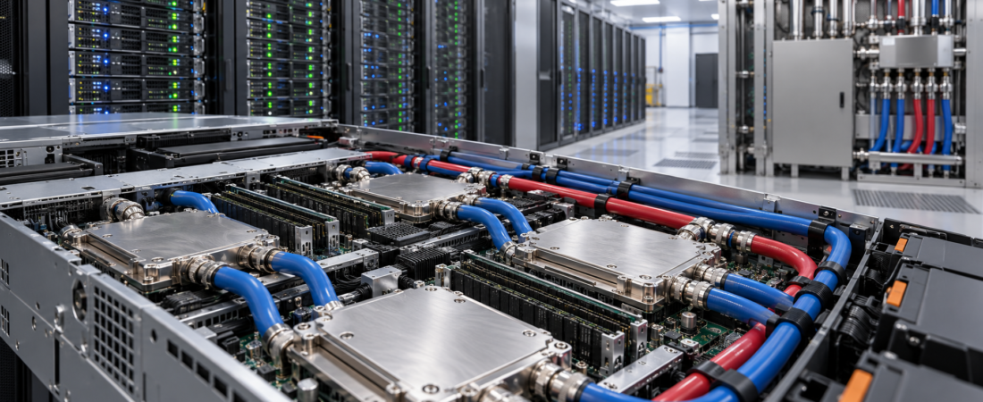
Direct-to-chip liquid cooling moves heat away from processors using liquid circulated through cold plates attached to heat-producing components. For data center operators evaluating dense AI and high-performance computing systems, the technology can change the cooling path from the server all the way to the facility’s heat-rejection equipment.
The decision is not simply whether liquid can remove heat. Operators must understand which components are cooled, how the server connects to the facility, what happens during a leak or pump failure, and whether the overall system meets reliability, water, energy, and maintenance goals.
How Direct-To-Chip Liquid Cooling Works
In a typical direct-to-chip design, cold plates sit against high-power components such as CPUs or GPUs. Coolant passes through channels in the plates, absorbs heat, and returns through hoses and manifolds. The heated liquid then transfers its energy through a heat exchanger to another cooling loop.
A coolant distribution unit, commonly called a CDU, often manages part of this exchange. Depending on the design, a CDU can include pumps, controls, filtration, instrumentation, and a heat exchanger. It may serve a rack or a group of racks, and its exact configuration depends on the IT equipment and facility design.
The U.S. Department of Energy describes a simplified arrangement in which a recirculating liquid loop collects heat from IT equipment and transfers it through a CDU to a facility cooling loop. The facility still needs a way to reject that heat, which may involve cooling towers or another suitable system.
Direct-to-chip cooling is different from immersion cooling, in which equipment is placed in a dielectric liquid. It also does not necessarily remove every watt of heat from a server. Memory, storage, power supplies, networking devices, and other components may continue to release heat into the room, so an air-cooling strategy is still required unless the equipment design specifies otherwise.
Start With The Workload And The Rack
Begin with the actual equipment plan rather than a generic rack-density target. Obtain the server manufacturer’s expected power draw, peak conditions, cooling interfaces, coolant specifications, and required supply temperatures and flow rates. Include networking and storage equipment in the rack or adjacent row.
Operators should distinguish installed electrical capacity from expected operating load. A system may have a high nameplate rating but spend much of its time at a lower load. Conversely, a power and cooling design based only on average consumption can fail to accommodate short peaks or future equipment changes.
Ask the equipment vendor how much of the server’s heat is captured by liquid and how much remains in the room. Use those figures to develop separate liquid-side and air-side heat budgets. Both budgets matter when sizing equipment, testing redundancy, and deciding whether an existing white space can accommodate the deployment.
Follow The Heat To The Facility Boundary
A useful design review follows the complete heat path: processor, cold plate, server hoses, rack manifold, CDU, facility loop, and final heat rejection. At each boundary, document who supplies the equipment, who owns maintenance, and what conditions the next component must accept.
Temperature And Flow
Confirm the allowable coolant supply-temperature range, required flow, pressure limits, and expected temperature rise through the IT equipment. These values should come from the equipment suppliers and be checked across normal operation and credible failure scenarios.
Warmer liquid temperatures can create opportunities to use different heat-rejection approaches or recover heat, but the benefit depends on local climate, facility design, and the temperature required by the server. Do not assume that a warm-water label guarantees an efficiency improvement.
Coolant And Materials
Coolant chemistry and material compatibility need deliberate control. The operator should obtain requirements for water quality, additives where applicable, filtration, sampling, and acceptable materials. A closed loop can still require monitoring and maintenance; it should not be treated as maintenance-free.
Review how the chosen fluid interacts with cold plates, seals, hoses, manifolds, and heat exchangers. Define procedures for filling, flushing, draining, replacing components, and disposing of fluids in accordance with the applicable supplier instructions and local requirements.
Design For Leaks, Service, And Failure
Liquid systems add connections and components that need inspection. A practical risk assessment should identify where a leak could occur, what equipment might be affected, how the leak would be detected, and who can isolate the affected section.
Leak-detection placement should reflect the actual installation: connection points, manifolds, CDUs, and routes where liquid could collect. Detection must be paired with an action plan. An alarm has limited value if staff do not know whether to isolate a loop, shut down equipment, or escalate to a vendor.
Plan service access before racks are installed. Technicians may need room to disconnect hoses, remove servers, reach valves, and handle spills. Confirm which connections are designed to be serviced while the system is operating and what conditions require a shutdown. Follow the manufacturer’s procedures rather than assuming that every quick disconnect is interchangeable or suitable for live service.
Reliability planning should also cover pump failure, loss of facility cooling, power interruption, control-system failure, and a blocked or restricted flow path. Determine whether the IT equipment will throttle, transfer workload, or shut down, and test whether those responses fit the organization’s availability objectives.
Evaluate Redundancy Across The Whole System
Redundant pumps or CDUs can reduce exposure to individual equipment failures, but redundancy at one layer does not eliminate common dependencies elsewhere. A shared power feed, control system, valve, pipe section, or heat exchanger can still affect multiple racks.
Map the failure domains from the IT equipment to the facility plant. For each credible failure, record the affected capacity, detection method, expected response time, and recovery procedure. Then compare the result with workload requirements: a training job that can be restarted may tolerate a different interruption profile from a service with strict availability commitments.
Commissioning should include integrated testing, not just component acceptance. Operators can use controlled tests to verify alarms, isolation, standby equipment, control sequences, and communication between the IT and facilities teams. The test plan should be agreed with vendors and performed within equipment safety limits.
Measure Energy And Water Together
Direct liquid cooling can change fan energy, pumping energy, chiller operation, and the way heat is rejected. The net result depends on the complete installation. Compare designs using a consistent workload, operating profile, climate, and measurement boundary rather than relying on a single vendor efficiency claim.
Power usage effectiveness, or PUE, compares total facility energy with IT equipment energy. It is useful for tracking facility overhead, but it does not by itself describe water consumption, the productivity of the computing equipment, or every environmental effect of a cooling design.
Water use deserves a separate review. A closed liquid loop at the rack does not automatically mean that the facility uses no water: the heat-rejection system may use evaporative cooling. Conversely, a design that reduces water consumption may have different energy or maintenance requirements. The Department of Energy notes that water-treatment choices can affect both energy use and operations.
For a fair comparison, ask designers to estimate annual electricity and water use across expected conditions, including peak weather, part-load operation, treatment equipment, and maintenance. State whether estimates cover only on-site water or include a broader boundary, and keep assumptions visible when comparing proposals.
Build A Cross-Functional Operating Model
Liquid cooling crosses traditional ownership boundaries. Facilities teams manage plant and distribution; IT teams manage servers and workloads; vendors may maintain specialized components. Establish a responsibility matrix before procurement so that each team knows who monitors coolant conditions, responds to alarms, authorizes isolation, and approves a return to service.
Training should include routine inspections and abnormal events. Staff need access to current diagrams, valve labels, equipment manuals, replacement parts, and vendor contacts. Change-control procedures should cover new server types and changes to coolant, hoses, set points, or rack layouts.
Procurement contracts should address compatibility, support availability, spare parts, maintenance intervals, and the process for resolving faults that span the IT and facility interfaces. Ask suppliers to identify required consumables and any equipment that cannot be substituted without retesting or approval.
Before expanding a pilot, compare measured temperatures, flow rates, alarms, maintenance activity, and workload interruptions against the original agreed project acceptance criteria. Document any differences and assign clear owners to resolve them. Repeat the review after changes to server models or facility controls, because a successful initial deployment does not guarantee that every later configuration will operate under identical conditions.
A Practical Evaluation Checklist
- Document rack power, peak load, and the proportion of heat removed by liquid.
- Verify coolant, temperature, flow, pressure, and material requirements for every interface.
- Map the heat path and remaining air-cooling load through to final heat rejection.
- Identify leak detection, isolation, service clearances, and response procedures.
- Test failure domains and redundancy against workload recovery objectives.
- Compare annual energy, water, maintenance, and capital costs using consistent assumptions.
- Assign ownership across IT, facilities, operations, and suppliers.
- Commission the integrated system and document lessons before expanding deployment.
Conclusion
Direct-to-chip liquid cooling gives operators another way to move heat from dense computing equipment, but its success depends on the entire system around the cold plate. A disciplined evaluation links server requirements to facility capacity, maintenance, reliability, and measurable operating outcomes.
Start with a defined workload and a testable design. Then use commissioning and operational data to decide whether the approach is ready to scale across additional racks or facilities.