
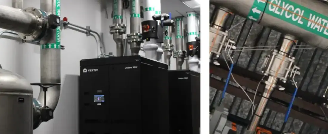
Closed-loop liquid cooling is becoming a practical requirement for many AI data centers as GPU and accelerator densities push beyond the comfortable limits of conventional air cooling. The technology moves heat away from processors through a controlled liquid circuit, typically using cold plates, manifolds, pumps, and coolant distribution units, or CDUs. For operators, however, the move to liquid is not simply a component swap. It changes facility design, maintenance, water strategy, controls, commissioning, and the relationship between IT and mechanical infrastructure.
Executive Summary
Closed-loop liquid cooling circulates coolant through a sealed technology loop that collects heat from CPUs, GPUs, memory, networking components, or other high-density equipment. In direct-to-chip systems, cold plates sit on the hottest components and transfer heat into the coolant. A CDU then manages the technology loop while exchanging heat with the facility cooling system.
This architecture can support far higher rack densities than traditional air cooling and can reduce dependence on server fans and room-level airflow. NVIDIA says its Rubin-generation infrastructure uses a fully liquid-cooled architecture, while Schneider Electric’s Motivair business is scaling CDU capacities into the megawatt range for AI factories.
The challenge is integration. Operators must decide coolant temperatures, flow rates, redundancy, leak detection, water chemistry, heat rejection, controls, service procedures, and how much residual air cooling remains necessary. The strongest designs treat liquid cooling as a facility system rather than an accessory attached to servers.
How Closed-Loop Liquid Cooling Works
In a typical direct-to-chip deployment, coolant flows through cold plates mounted on processors and other high-heat components. The heated coolant leaves the server through hoses or quick disconnects, passes through rack or row manifolds, and returns to a CDU.
The CDU circulates coolant, maintains pressure and flow, monitors temperatures, and transfers heat to the facility water system through a heat exchanger. This creates two hydraulically separated loops: the technology loop serving IT equipment and the facility loop carrying heat toward chillers, dry coolers, cooling towers, or other heat-rejection equipment.
Why AI Is Accelerating Closed-Loop Liquid Cooling
AI workloads concentrate enormous computing power into relatively small spaces. GPUs operate at high utilization for long periods, and rack-scale architectures combine accelerators, CPUs, memory, switches, and power electronics in dense systems. Moving that heat through air becomes increasingly difficult as density rises.
Direct-to-chip cooling attacks the problem at the source. Instead of heating room air and then removing that heat, liquid captures a large share of the thermal load directly from the components generating it. This can allow higher rack density while reducing the heat managed by room-level air systems.
Why the CDU Is Critical to Closed-Loop Liquid Cooling
Once liquid cooling supports production AI workloads, the CDU becomes as operationally important as other mechanical systems serving the data hall. A failure that reduces coolant flow can affect an entire rack, row, or cluster quickly.
Capacity planning therefore needs more than a headline kilowatt rating. Operators should evaluate pump redundancy, heat-exchanger capacity, control architecture, filtration, service access, pressure limits, flow stability, and behavior during partial failures.
Scale is increasing rapidly. Motivair by Schneider Electric introduced a 2.5MW CDU in 2026 and says its centrally controlled portfolio can scale beyond 10MW. That reflects the direction of AI facilities, where cooling may need to be managed at pod or hall scale rather than rack by rack.
Closed-Loop Liquid Cooling Does Not Mean Zero Water
One of the most important distinctions for decision-makers is between coolant consumption and facility water consumption.
In a closed technology loop, coolant is recirculated rather than continually discharged. That can greatly reduce the makeup fluid required within the IT cooling circuit. But the heat transferred out of that loop still needs to reach the environment.
If the facility rejects heat through evaporative cooling towers, it can still consume significant water even though the server-side loop is closed. If it uses dry coolers, the site can reduce water consumption but may require more electrical energy, larger equipment, or higher operating temperatures under difficult weather conditions.
How Warmer Coolant Improves Closed-Loop Liquid Cooling
Higher coolant temperatures can make heat rejection easier and reduce dependence on mechanical chilling. NVIDIA says Vera Rubin NVL72 systems use 45-degree Celsius warm-water cooling, while its Rubin-generation infrastructure is designed around 100% liquid cooling.
The trade-off is that every component in the cooling chain must be designed for the intended temperature range. Operators cannot simply raise temperatures without validating server specifications, pump performance, materials compatibility, controls, and environmental conditions.
Closed-Loop Liquid Cooling: Chemistry and Leak Detection
A closed loop reduces exposure to contaminants, but it does not remove the need for fluid management. Corrosion, particulates, incompatible metals, dissolved gases, and poor water chemistry can damage pumps, heat exchangers, seals, and cold plates.
Operators need clear coolant specifications from equipment vendors and a maintenance program that includes sampling, filtration, treatment, and inspection. Quick disconnects, hoses, manifolds, seals, and fittings deserve the same rigor as other critical infrastructure.
Leak detection should also be designed in rather than added later. Moisture sensors, drip trays, pressure monitoring, flow monitoring, automatic valves, and alarms can identify abnormal conditions. Teams should know whether a rack can be isolated without shutting down an entire loop and whether workloads can migrate before thermal limits are reached.
Retrofitting Closed-Loop Liquid Cooling Is Harder
New facilities can design liquid cooling into the building from the start. Existing data centers face a more difficult task.
A retrofit may require new pipework, CDUs, pumps, heat exchangers, controls, leak detection, maintenance space, and changes to the facility water system. Operators may also need to support liquid-cooled AI racks alongside older air-cooled equipment in the same building.
For colocation providers, this becomes a commercial issue. Customers increasingly ask not only how many kilowatts a rack can receive, but whether liquid cooling is available, what supply temperatures are supported, where the CDU sits, who owns it, and how maintenance responsibility is divided.
Single-Phase And Two-Phase Designs Have Different Trade-Offs
Most current direct-to-chip systems use single-phase liquid cooling, in which the coolant remains liquid as it absorbs heat. Schneider Electric describes single-phase cold-plate cooling as the current default because it is comparatively straightforward to deploy and aligns with existing server and facility designs.
Two-phase direct-to-chip systems allow a working fluid to change phase as it absorbs heat. The phase change can move large amounts of heat efficiently, but the architecture is more specialized and can introduce additional cost, component requirements, and operating complexity.
Closed-Loop Liquid Cooling Needs Clear Ownership
Liquid cooling crosses organizational boundaries that were previously easier to separate. Server teams, facility engineers, controls specialists, network teams, and equipment vendors may all interact with the same cooling chain.
Responsibility must therefore be explicit. Who owns the CDU? Who approves coolant chemistry? Who responds to a leak alarm? Who replaces a hose? Who validates cooling-control changes? Who decides whether a rack can return to service?
These questions should be resolved before commissioning. Methods of procedure and emergency operating procedures need to reflect the new mechanical dependencies, and technicians should train on realistic failure scenarios.
9 Critical Closed-Loop Liquid Cooling Checks
Before approving a closed-loop liquid cooling deployment, infrastructure leaders should complete these nine checks:
- Calculate liquid heat capture. Confirm what percentage of each rack’s heat enters the technology loop.
- Validate supply temperatures. Match coolant set points to server, CDU, and heat-rejection specifications.
- Size CDU capacity and redundancy. Model full load, maintenance conditions, and partial failures.
- Assess facility heat rejection. Confirm whether chillers, dry coolers, or cooling towers can handle the transferred load.
- Model total water use. Separate technology-loop makeup fluid from facility-side evaporative consumption.
- Define coolant chemistry. Establish approved fluids, sampling intervals, filtration, and treatment responsibilities.
- Test leak isolation. Verify alarms, automatic valves, rack isolation, and workload-migration procedures.
- Plan residual air cooling. Quantify the thermal load from components not connected to cold plates.
- Assign operational ownership. Document responsibility across IT, facilities, colocation providers, and vendors.
Technology Loop
- Key question: Can flow and pressure remain stable during equipment failures?
- Evidence to review: Pump curves, redundancy design, pressure limits, and commissioning-test results.
Facility Loop
- Key question: Can the site reject the full thermal load during worst-case weather?
- Evidence to review: Seasonal thermal models, equipment capacities, supply temperatures, and contingency performance.
Operations and Leak Response
- Key question: Can teams isolate a leak without losing the entire AI cluster?
- Evidence to review: Alarm logic, automatic-valve behavior, isolation procedures, staff training, and emergency drills.
The review should connect cooling to the wider infrastructure strategy. Related considerations include power-led data center site selection, data center microgrid architecture, 800G Ethernet planning for AI clusters, data center outage prevention, and the facility demands of modern AI factories.
Future Outlook
Liquid cooling is likely to become more deeply integrated into AI infrastructure as accelerator densities continue to rise. NVIDIA’s Rubin architecture, the growth of megawatt-class CDUs, and industry work around standardized manifolds and interfaces all point toward cooling becoming a planned part of rack-scale system design.
The facilities best positioned for future AI systems will be those that can support changing coolant temperatures, higher flow requirements, modular CDU capacity, and new rack generations without rebuilding the entire mechanical plant each time silicon advances.
Frequently Asked Questions
What Is Closed-Loop Liquid Cooling?
Closed-loop liquid cooling circulates coolant repeatedly through a sealed circuit rather than continually consuming and discharging it. In direct-to-chip systems, that coolant flows through cold plates and transfers heat through a CDU to the facility cooling system.
Does Closed-Loop Cooling Eliminate Water Use?
No. It can reduce coolant consumption inside the technology loop, but the facility may still use water to reject heat through cooling towers or other evaporative systems. Total water use depends on the complete cooling architecture.
Do Liquid-Cooled Racks Still Need Air Cooling?
Many current direct-to-chip systems still require some air cooling for components not connected to cold plates. Fully liquid-cooled architectures are emerging, but operators should confirm the residual air load for each platform.
Conclusion
Closed-loop liquid cooling is becoming one of the defining infrastructure technologies of the AI data center. It enables rack densities that are increasingly difficult to support with air alone and can create new opportunities for efficient heat rejection and reduced server-fan energy.
But the technology does not make cooling simple. It moves the problem into a new architecture built around pumps, CDUs, manifolds, fluid quality, controls, heat exchangers, leak response, and facility heat rejection.
For CIOs, CTOs, and data center operators, the key question is therefore not whether liquid cooling can remove the heat. It is whether the organization can operate the entire cooling chain reliably, maintainably, and efficiently as AI hardware changes.